Metal Injection Molding is a net-shape process for producing solid metal parts that combines the design freedom of plastic injection molding with material properties near that of wrought metals. With its inherent design flexibility, MIM is capable of producing an almost limitless array of geometries in many different alloys.
An emphasis on plastic part design flexibility should be applied to metal part geometries developed with the MIM process in mind. Traditional metalworking technology limitations should be ignored. The MIM process can allow significant shape sophistication, the combination of multiple parts, multiple feature/functions within a single component, product assembly enhancement features, miniaturization of mechanical assemblies, mass reduction, and custom tailored physical properties for the intended end use are all possibilities with MIM. So MIM offers you more design freedom and material options than many other manufacturing processes.
The MIM design guide is intended to serve as a reference for applying MIM design principles to new components and evaluating existing components for possible conversion to this manufacturing technology. Properly designed MIM parts maximize the economic benefits of the process by ensuring that net shape results and targeted dimensional Cpk’s are attained.
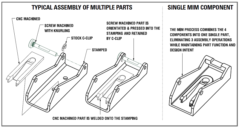
Single Component
A very effective way of utilizing MIM’s inherent design freedom is to combine multiple components in an assembly into a single MIM component.
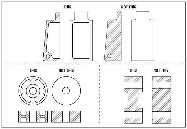
Uniform Wall Thickness
Maintaining a uniform wall thickness throughout a component reduces the likelihood of molding process flaws, thus improving the overall part quality, cosmetics, and the resulting dimensional tolerances.
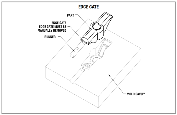
Gating
In general, the gate is placed at the thickest cross-section to allow the material to flow from thick to thin cross-sections. Additionally, the location of the gate(s) should be placed to allow uniform filling of the mold cavity.
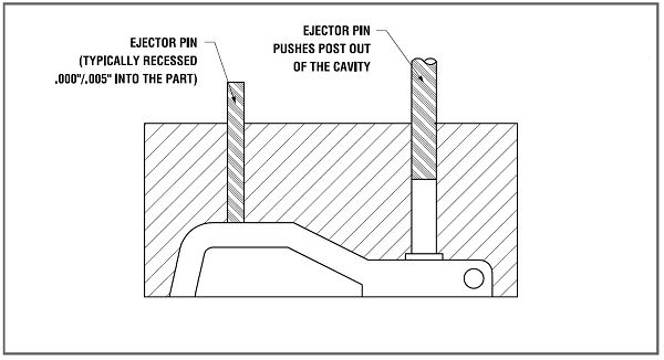
Ejection
Once the molded part has cooled it must be ejected, the ejector pins push the part out of the cavity. The location and number of ejector pins depend on the component size, binder strength, and tooling complexity. Knock-out ejector pins are usually required for removing parts from the mold, and good design of these pins is critical to minimise flash marking of the parts.
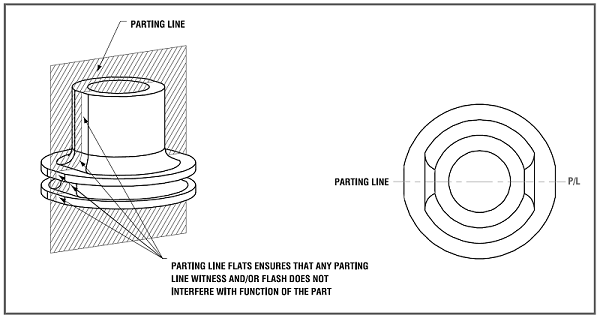
Parting Lines
The parting line location is one important decision in MIM tooling design. The parting line is the trace left on the molded component surface where the mold sections meet. Cosmetic and functional requirements may help guide parting line location.
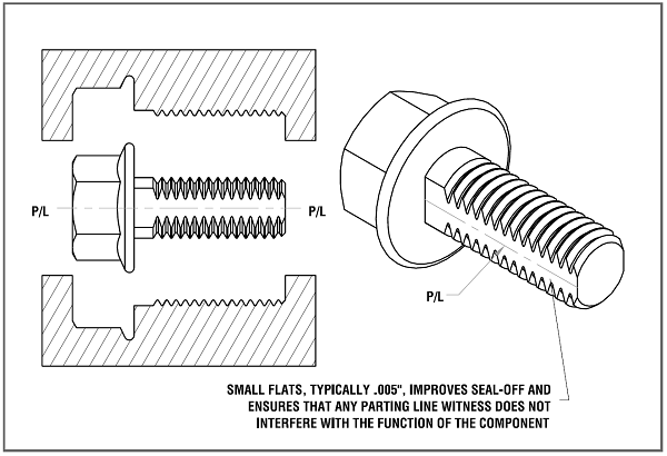
Threads
Internal threads can be molded directly into the component using unscrewing cores.
External threads can be molded directly onto the component thus eliminating the need for secondary thread-forming operations.
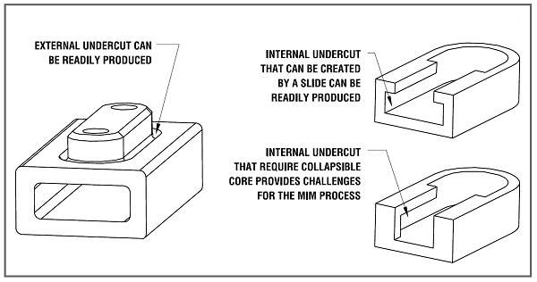
Undercuts
External undercuts can be produced readily with the MIM process.
Internal undercuts that can be produced with a mechanical or hydraulic actuated slide can be readily produced.