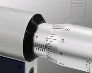
 Metal Injection Molding tolerances are nominally ±0.3%-0.5%, although tighter tolerances can be achieved in some cases if deemed essential. MIM component production ranges over a large size range, making it difficult to address tolerances directly over such a wide range. In some instances, the choice has been to create a table of tolerance versus size, showing capabilities as follows: These MIM tolerances can be obtained within a single batch but wider variation is usually observed over time.
- ± 0.03 mm (0.0012 inch) for features below 3 mm (0.12 inch)
- ± 0.05 mm (0.002 inch) for features between 3 and 6 mm (0.12 to 0.25 inch)
- ± 0.08 mm (0.003 inch) for features between 6 and 15 mm (0.25 to 0.6 inch)
- ± 0.15 mm (0.006 inch) for features between 15 and 30 mm (0.6 to 1.2 inch)
- ± 0.25 mm (0.01 inch) for features between 30 and 60 mm (1.2 to 2.4 inch).
| feature | best possible ± | nominal or typical ± |
|---|---|---|
| absolute dimension | 0.025 mm (0.001 inch) | 0.05 mm (0.002 inch) |
| Angle | 0.05° | 2° |
| density | 0.2% | 1% |
| dimension | 0.05% | 0.3% |
| flatness | 0.1% | 0.2% |
| hole diameter | 0.04% | 0.1% |
| hole location | 0.1% | 0.3% |
| parallelism | 0.2% | 0.3% |
| perpendicularity | 0.1% or 0.1° | 0.2% or 0.3° |
| roundness | 0.3% | 0.3% |
| surface roughness | 0.2 µm (8 µ inch) | 0.8 µm (32 µ inch) |
| weight | 0.1% | 0.4% |
| corner radius | 0.1 mm (0.004 inch) | 0.15 mm (0.006 inch) |
