Although many of these design guidelines are similar to those used for plastic injection molding, there are subtle differences in how MIM components are designed to account for the subsequent thermal processing. For example, wall sections should not exceed a certain thickness to prevent defect formation during thermal debinding and a flat section is often designed into the component to provide uniform support for sintering. These design concepts and many others are described here as suggestions to provide guidance, since many potential components will not perfectly fall into the ideal design. As such, the opportunity exists to find clever solutions outside the advice provided here to take advantage of the MIM technology for particular applications.
Metal injection molding is a process by which powder is shaped into complex components using tooling and injection molding machines that are very similar to those used in plastic injection molding. Therefore, the component’s complexity is of the same magnitude as those seen in plastic injection molding. The artifacts associated with the injection molding process (gates, ejector pins, parting line) are also similar to those seen in plastic injection molding and must be accounted for in design. However, since the MIM process requires multiple post-molding debinding and sintering steps, some design considerations such as cross-sectional thickness
and geometry features require consideration.
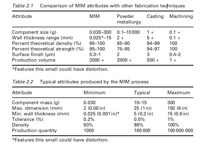
As a general rule of thumb, components that are less than approximately 100 g and fit into the palm of your hand could be good candidates for MIM technology. A mean size of 15 g is typical for a MIM component; however,components in the range around 0.030 g are possible. Table 2.1 compares the MIM process with other manufacturing processes. Notice that MIM is limited to smaller part sizes, can provide thinner wall thicknesses, has excellent surface finish and is suited for high volumes. Table 2.2 reviews the upper and lower specifications of the MIM process.
The following are some general design considerations which will be discussed in detail in this chapter.
. Avoid components over 12.5mm (0.5 in) thick. This is a function of MIM technology and alloy, for example 4140 and alloys that use carbonyl powder can have thicker wall sections than those that use gasatomized powders that have larger particles. Also modifications to binder systems can be made to allow thicker sections to debind.
. Avoid components over 100 g in mass; however, 300 g are possible for some technologies.
. Avoid long pieces without a draft (28) to allow ejection.
. Avoid holes smaller than 0.1mm (0.0039 in) in diameter.
. Avoid walls thinner than 0.1mm (0.0039 in), although 0.030mm walls are possible in some cases.
. Maintain uniform wall thickness; thin, slender sections attached to thick sections should be avoided to enhance flow during molding, to avoid sinks and voids, and to limit distortion during sintering.
. Core out thick areas to avoid sinks, warpage, and debinding defects.
. Avoid sharp corners. The desired radius is greater than 0.05mm(0.002 in).
. Design with a flat surface to aid in sintering – otherwise custom ceramic setters required.
. Avoid inside closed cavities – although some technologies such as a chemically or thermally removable polymer core may be used but is not common.
. Avoid internal undercuts – although a collapsible core or extractible core mentioned above could be used but are not common.
. Design with lettering – raised or recessed.
. Design with threads – internal and external.