 The simplest Metal Injection Molding (MIM) shape is produced in a mold made of two sections with plane surfaces that meet to seal off the cavity. One section consists of a core which fits into an impression in the other section with uniform clearances that produce shapes with uniform wall thicknesses. The core produces the internal features while the impression produces the external features. All features are designed to permit the cavity to release the solidified form, which is pushed off the core with ejector or knock-out pins.
Increased complexity in MIM components can be achieved with the addition of slides, cores, and other tools commonly used in plastic injection molding. While added features, along with their increased complexity, can have economic benefits by eliminating secondary processes or assembly operations, they typically entail additional costs associated with tooling and start-up engineering. These benefits and costs must be carefully weighed against each other at every stage of the design. A MIMA-member parts fabricator is best equipped to provide help with this assessment.
There are many critical aspects that must be considered when designing a MIM component in order to take full advantage of all the benefits of the process. A clear understanding of these considerations as you work closely with your MIM parts fabricator will insure the best possible manufacturing results for your component.
Click on any MIM design topic below for a discussion of its essential details.
| Uniform wall thickness | Holes and slots |
| Thickness transition | Undercuts |
| Coring holes | Gating |
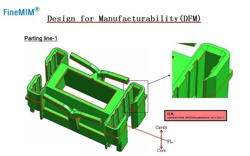
| Draft | Parting lines |
| Ribs and webs | Decorative features |
| Fillets and radii | Sintering support |
| Threads |